Основные технические параметры и конструкция
Определение и выбор свинца: Модели со значением свинца более 1/3 или даже 1/2 диаметра вала винта обычно классифицируются как большие свинцовые шариковые винты. Например, для шарико-винтовой передачи Φ20 мм шаг более 10 мм можно считать большим шагом.
Согласование скорости и двигателя: его конструкция направлена на снижение зависимости от высоких скоростей двигателя. Высокоскоростное движение может быть достигнуто с помощью двигателей с обычной скоростью, что снижает требования к двигателю и водителю, делая его более экономически эффективным.
Соображения точности: Стандартная точность обычно составляет класс C7. При выборе модели основное внимание следует уделять точности повторяющегося позиционирования, а не кумулятивной ошибке свинца, поскольку ее высокоскоростные характеристики часто используются для быстрого управления "точка-точка", а не для сверхточной резки.
Конструктивные особенности: В конструкции гайки часто используется несколько рядов шарикоподшипников для увеличения количества несущих шариков, компенсируя потенциальное снижение грузоподъемности из-за увеличения свинца.
Приложения
Шариковый винт серии SFY является идеальным выбором для следующих применений с приоритетом скорости:
Высокоскоростная автоматизация и обработка: быстрая передача материалов на автоматизированных производственных линиях, захватные оси высокоскоростных роботов (например, роботов Delta) и подъемные механизмы тележек AGV.
Механизмы быстрой подачи: оси быстрого перемещения (G00) станков с ЧПУ, холостое перемещение станков лазерной резки и оси сканирования испытательного оборудования в отрасли 3C.
Специальное оборудование: высокоскоростное упаковочное оборудование, механизмы подачи печатного оборудования и сценическое подъемное оборудование.
Любое применение, требующее сокращения времени простоя, увеличения времени цикла работы оборудования и повышения эффективности производства.
Шариковый винт серии Big Lead SFY — это «ускоритель» скорости оборудования. Благодаря продуманному преобразованию механической конструкции он эффективно преобразует вращательное движение в высокоскоростное линейное движение, что напрямую позволяет оборудованию достигать более быстрых производственных циклов. Выбор серии SFY означает выбор «скорости» и «эффективности» в качестве основных конкурентных преимуществ вашего оборудования в условиях сегодняшней жесткой рыночной конкуренции.
Параметры
Большой свинец
Модель №. | д | Я | Да | Размер | Номинальная нагрузка | Жесткость | Вес |
| Д | А | Е | Б | Л | В | Х | Х | КВ | н | Са(кгс) | Коа(кгс) | Кгф/мкм | Кг |
| SFY1616-3.6 | 16 | 16 | 2.778 | 32 | 53 | 10.1 | 10 | 45 | 42 | 34 | 4.5 | М6 | 1,8х2 | 1073 | 2551 | 31 | 0.238 |
| SFY2020-3.6 | 20 | 20 | 3.175 | 39 | 62 | 13 | 10 | 52 | 50 | 41 | 5.5 | М6 | 1,8х2 | 1387 | 3515 | 37 | 0.38 |
| SFY2525-3.6 | 25 | 25 | 3.969 | 47 | 74 | 15 | 12 | 64 | 60 | 49 | 6.6 | М6 | 1,8х2 | 2074 | 5494 | 45 | 0.652 |
| SFY3232-3.6 | 32 | 32 | 4.762 | 58 | 92 | 17 | 12 | 78 | 74 | 60 | 9 | М6 | 1,8х2 | 3021 | 8690 | 58 | 1.168 |
| SFY4040-3.6 | 40 | 40 | 6.35 | 73 | 114 | 19.5 | 15 | 99 | 93 | 75 | 11 | М6 | 1,8х2 | 4831 | 14062 | 70 | 2.288 |
| SFY5050-3.6 | 50 | 50 | 7.938 | 90 | 135 | 21.5 | 20 | 117 | 112 | 92 | 14 | М6 | 1,8х2 | 7220 | 21974 | 86 | 4.12 |
Двойной провод
Модель №. | д | Я | Да | Размер | Номинальная нагрузка | Жесткость | Вес |
| Д | А | Е | Б | Л | В | Х | Х | КВ | н | Са(кгс) | Коа(кгс) | Кгф/мкм | Кг |
| SFY1632-1.6 | 16 | 32 | 2.778 | 32 | 53 | 10.1 | 10 | 42.5 | 42 | 34 | 4.5 | М6 | 0,8х2 | 493 | 1116 | 11 | 0.222 |
| SFY2040-1.6 | 20 | 40 | 3.175 | 39 | 62 | 13 | 10 | 48 | 50 | 41 | 5.5 | М6 | 0,8х2 | 653 | 1597 | 15 | 0.348 |
| SFY2550-1.6 | 25 | 50 | 3.969 | 47 | 74 | 15 | 12 | 58 | 60 | 49 | 6.6 | М6 | 0,8х2 | 976 | 2495 | 19 | 0.596 |
| SFY3264-1.6 | 32 | 64 | 4.762 | 58 | 92 | 17 | 12 | 71 | 74 | 60 | 9 | М6 | 0,8х2 | 1374 | 3571 | 22 | 1.066 |
| SFY4080-1.6 | 40 | 80 | 6.35 | 73 | 114 | 19.5 | 15 | 90 | 93 | 75 | 11 | М6 | 0,8х2 | 2273 | 6387 | 29 | 2.096 |
| SFY50100-1,6 | 50 | 100 | 7.938 | 90 | 135 | 21.5 | 20 | 111 | 112 | 92 | 14 | М6 | 0,8х2 | 3398 | 9980 | 35 | 3.818 |
Рисунки
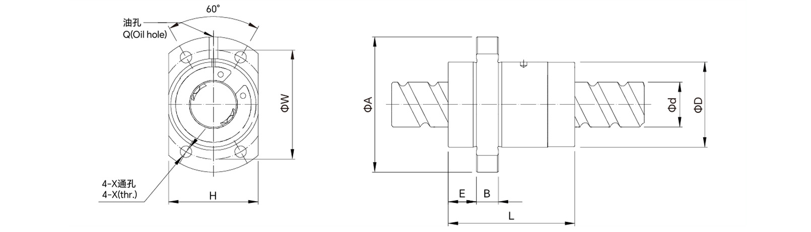
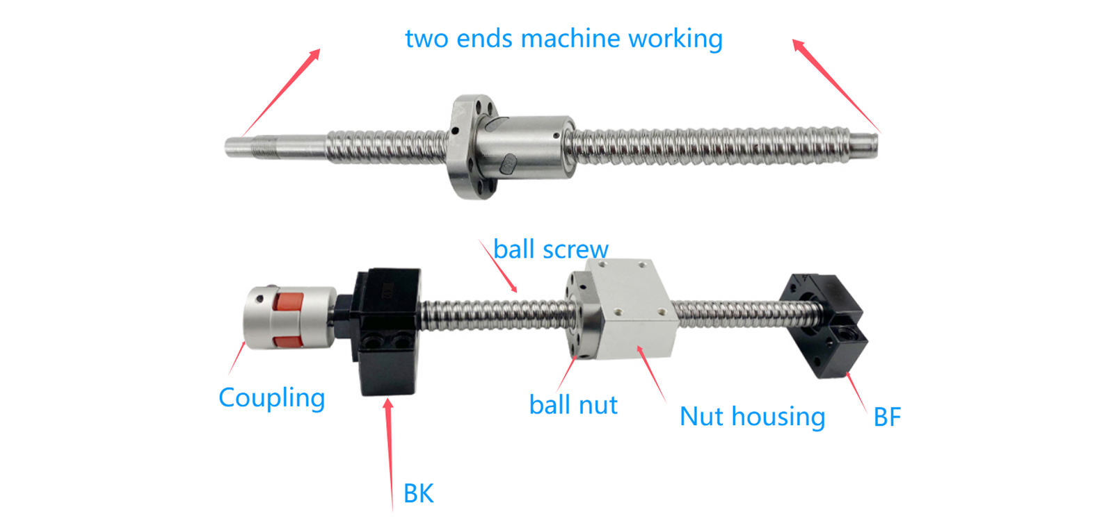
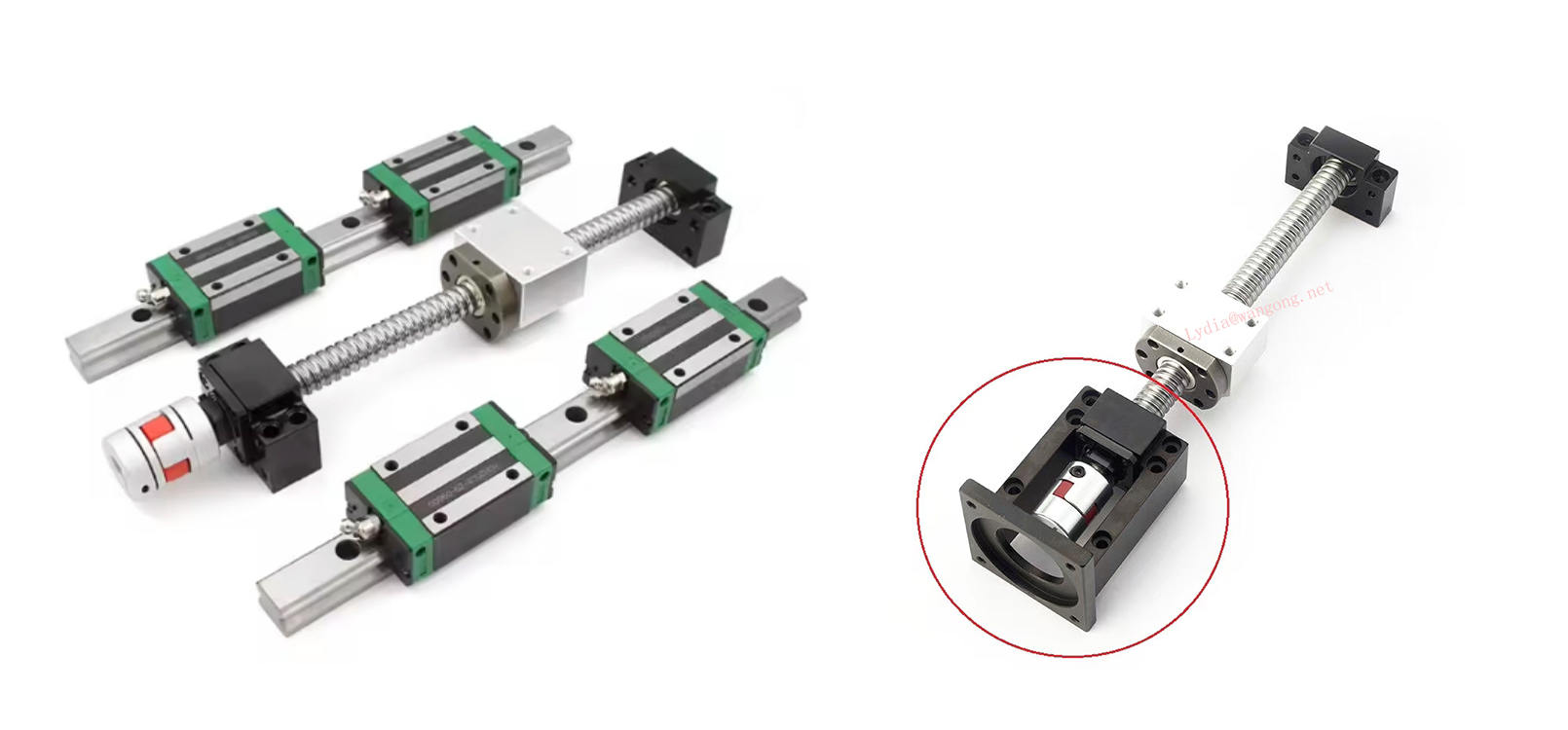
Поддерживает выбор комбинации продуктов
Production Capacity
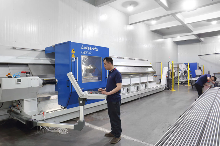 |
Cyclone Milling Machines
LWN160-6000mm Leistritz Cyclone milling machines imported directly from
Germany, the ball screw shaft precision can be C3, C5, and C7 the max length
can be 7000mm |
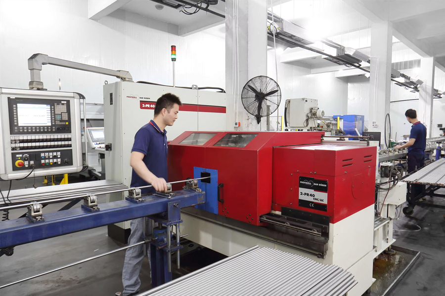
Rolled Thread CNC Machines
PR-40CNC Profiroll rolled thread ball screw machines imported directly from
Germany the ball screw shaft precision can be C5, C7 -C10 |
|
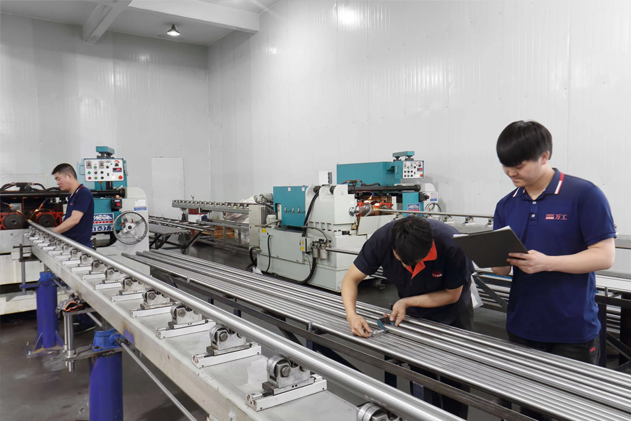 |
Rolled Thread CNC Machines
ST-20.2 and ST-347.7 rolled thread ball screw machines from TaiWan.
The ball screw shaft precision can be C7 - C10 |
Ball Screw Assembly Workshop
We conduct nut assembly in a constant temperature workshop, all workers
having decades of work experience and zero clearance between the screw
and nut. |
 |
 |
Ball Screw Assembly Workshop
One ball screw shaft matches one ball screw nut. Because each ball screw
shaft has a very tiny different tolerance. There are dozens of different
ball sizes for different screw shaft.
Our ball screw shaft and nut can be interchanged with the Taiwan
TBI ball screw shaft and nut very well. |
Model Code Explanation
| ①Nominal Model |
| S |
F |
I |
| S: Single nut |
D: Double nut |
O: Off set double nut |
F: With flange |
C: Without flange |
NI: NI type nut |
| U |
| NU: NU type nut |
A: A type nut (A solution for slide table) |
Y: Y type nut |
U: DIN type nut |
K: K type nut |
S: S type nut (A solution for slide table) |
| ②Threading Direction |
③Nominal Diameter |
④Lead |
| L: Left |
R: Right |
Unit:mm |
|
| ⑤Number of Turns (Turn·Row) |
| Turn:T:1 |
A:1.5(or 1.7/1.8) |
B:2.5/2.8 |
C:3.5 |
D:4.8 |
ex:(2.5x2 =B2) |
| ⑥Flange Type |
| N: Not cutting |
S: Single cutting |
D: Double cutting |
| ⑦Product Code |
⑧Accuracy Grade |
⑨Overall Length of Shaft |
| G: Grind |
F: Rolled |
C0, C1, C2, C3, C5, C7, C10 |
Unit: mm |
| ⑪ |
⑫ |
| Axial Clearance and Preload Value |
Number of Nut |
| PO, P1, P2, P3, P4 |
(Leave blank if only one nut is required)
Ex:Install two nuts on a shaft B2 |
| ⑬ |
⑭ |
| Nut Surface Treatment |
Shaft Surface Treatment |
| S: Standard |
S: Standard |
| B1: Black Oxidation |
B1: Black Oxidation |
| N1: Hard Chrome Plating |
N1: Hard Chrome Plating |
| N3: ickel Plating |
N3: Nickel Plating |
Design Accuracy
1-1-1 Lead/Travel Accuracy
According to the standard of JIS,we classified our lead accuracy through E,e,e3oo and e2m four main regulations.As figure 1.1.1~1.1.3 shown in below, all the definition and tolerance are specified.To test the accumulated travel deviations for grade C7 and C10, the tolerance wll be chosen in random 30omm of useful length and evaluated if it is qualified with the e300 table of 1.1.3.
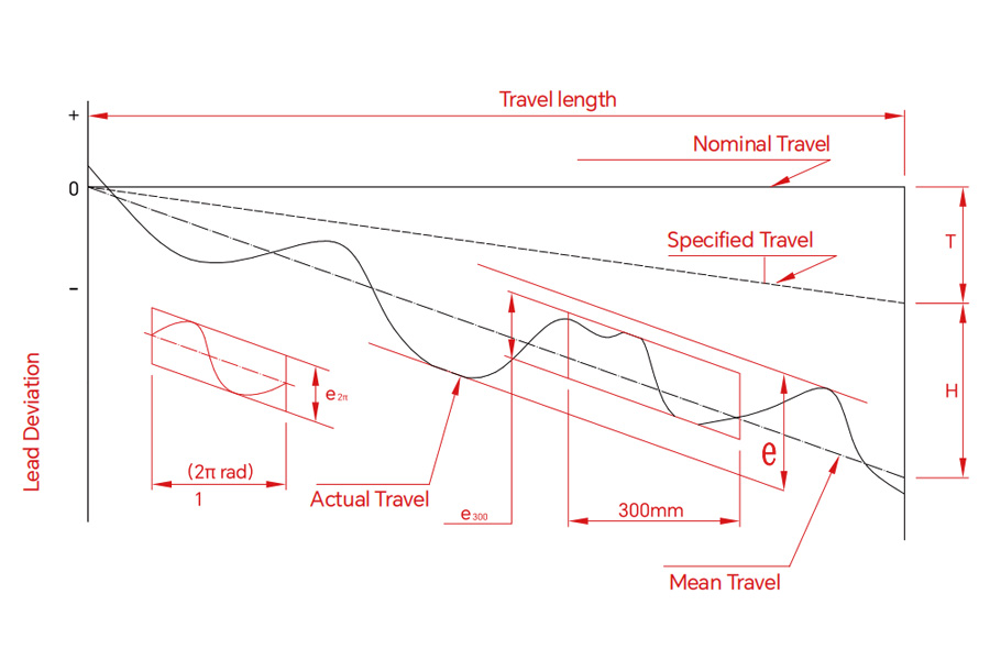
Fig 1.1.1 Diagram of Lead Accuracy
| Terms |
Reference |
Definition |
Allowable |
| Travel Compensation |
T |
Travel compensation is the deduction between specified and nominal travel in the useful travel.
A slightly smaller value compared with nominal travel is often selected by customer, to compensate for an expected elongation caused by temperature rise or external load.
Therefore"T "” is usually a negative value.
Note:if no compensation is needed,specified travel is the same as nominal travel. |
Table 1.1.2 |
| Actual Travel |
|
Actual travel is the axial displacement of the nut relative to the screw shaft. |
|
| Mean Travel |
|
Mean travelis the linear best fit line of actual. This could be obtained by the leastsquares method. This line represents the tendency of actual travel. |
|
| Mean Travel Deviation |
E |
Mean travel deviation is the deduction between mean travel and specified travel within travel length. |
|
| Travel Variations |
e

 |
Travel variations is the coverage of 2 lines drawn parallel to the mean travel.
Maximum width of variation within the travel length.
Actual width of variation for the length of 300mm taken anywhere within the travel length.
Wobble error, actual width of variation for one revolution (2πt radian) |
Table 1.1.2
Table 1.1.3
Table 1.1.3 |
Table 1.1.2 Mean Travel Deviation (±E) and Travel Variation (e) (JIS B 1192)
| Grade |
C0 |
C1 |
C2 |
C3 |
C5 |
C7 |
C10 |
| Travel Length (mm) |
Over |
Incl. |
±E |
e |
±E |
e |
±E |
e |
±E |
e |
±E |
e |
e |
e |
|
100 |
3 |
3 |
3.5 |
5 |
5 |
7 |
8 |
8 |
18 |
18 |
±50/300mm |
±210/300mm |
| 100 |
200 |
3.5 |
3 |
4.5 |
5 |
7 |
7 |
10 |
8 |
20 |
18 |
| 200 |
315 |
4 |
3.5 |
6 |
5 |
8 |
7 |
12 |
8 |
23 |
18 |
| 315 |
400 |
5 |
3.5 |
7 |
5 |
9 |
7 |
13 |
10 |
25 |
20 |
| 400 |
500 |
6 |
4 |
8 |
5 |
10 |
7 |
15 |
10 |
27 |
20 |
| 500 |
630 |
6 |
4 |
9 |
6 |
11 |
8 |
16 |
12 |
30 |
23 |
| 630 |
800 |
7 |
5 |
10 |
7 |
13 |
9 |
18 |
13 |
35 |
25 |
| 800 |
1000 |
8 |
6 |
11 |
8 |
15 |
10 |
21 |
15 |
40 |
27 |
| 1000 |
1250 |
9 |
6 |
13 |
9 |
18 |
11 |
24 |
16 |
46 |
30 |
| 1250 |
1600 |
11 |
7 |
15 |
10 |
21 |
13 |
29 |
18 |
54 |
35 |
| 1600 |
2000 |
|
|
18 |
11 |
25 |
15 |
35 |
21 |
65 |
40 |
| 2000 |
2500 |
|
|
22 |
13 |
30 |
18 |
41 |
24 |
77 |
46 |
| 2500 |
3150 |
|
|
26 |
15 |
36 |
21 |
50 |
29 |
93 |
54 |
| 3150 |
4000 |
|
|
30 |
18 |
44 |
25 |
60 |
35 |
115 |
65 |
| 4000 |
5000 |
|
|
|
|
52 |
30 |
72 |
41 |
140 |
77 |
| 5000 |
6300 |
|
|
|
|
65 |
36 |
90 |
50 |
170 |
93 |
| 6300 |
8000 |
|
|
|
|
|
|
110 |
60 |
210 |
115 |
| 8000 |
10000 |
|
|
|
|
|
|
|
|
260 |
140 |
| 10000 |
12500 |
|
|
|
|
|
|
|
|
320 |
170 |
Table 1.1.3 International standard of accuracy grade for ball screw
| Grade |
C0 |
C1 |
C2 |
C3 |
C5 |
C7 |
C10 |
|
3.5 |
5 |
7 |
8 |
18 |
50 |
210 |
|
2.5 |
4 |
5 |
6 |
8 |
|
|
1-1-2 Axial Play
Axial play of WANGONG's precision ball screw is shown below:
Table 1.1.4 Classification of Axial Play
| Grade |
P0 |
P1 |
P2 |
P3 |
P4 |
| Axial Play |
Yes |
No |
No |
No |
No |
| Preload |
No |
No |
Light |
Medium |
Heavy |
Excessive preload increases the friction torque and generates heat which wll reduce the life expectancy. However, insufficient preload will reduce stifness and increase the possibility of lost motion. WANGONG recommends that the preload applied on CNC machine tools should not heavier than 8% of the dynamic load; 5% for industrial automation X-Y table.
Table 1.1.5 The reference spring force of (P2)
| Model No. |
Spring Force (Kg) Single Nut |
Spring Force(Kg) Double Nut |
| 1605 |
0.1~0.3 |
0.3~0.6 |
| 2005 |
0.1~0.3 |
0.3~0.6 |
| 2505 |
0.2~0.5 |
0.3~0.6 |
| 3205 |
0.2~0.5 |
0.5~0.8 |
| 4005 |
0.2~0.5 |
0.5~0.8 |
| 2510 |
0.2~0.5 |
0.5~0.8 |
| 3210 |
0.3~0.6 |
0.5~0.8 |
| 4010 |
0.3~0.6 |
0.5~0.8 |
| 5010 |
0.3~0.6 |
0.8~1.2 |
| 6310 |
0.6~1.0 |
0.8~1.2 |
| 8010 |
0.6~1.0 |
0.8~1.2 |
Table 1.1.6 Axial Play (Po) Clearance in the Axial Direction of Rolled and Grind Ball Screw
| Nominal Diameter |
Rolled Ball Screw Clearance in the Axial Direction (max.) |
Ground Ball Screw Clearancein the Axial Direction (max.) |
| Φ04~Φ14 miniature ball screw |
0.05 |
0.015 |
| Φ15~Φ40 middle size of ball screw |
0.08 |
0.025 |
| Φ50~Φ100 big size of ball screw |
0.12 |
0.05 |
1-1-3 Definition of Mounting Accuracy and Tolerance on Ball Screw
The main items of the mounting accuracy of ball screw are listed in below.
(1) Periphery run-out of the supporting part of the screw shaft to the screw groove.
(2) Concentricity of a mounting portion of the shaft to the adjacent ground portion of the screw shaft.
(3) Perpendicularity of the shoulders to the adjacent ground portion of tha screw shaft.
(4) Perpendicularity of the nut flange to the axis of the screw shaft.
(5) Concentricity of the ball nut diameter to the screw groove.
(6) Parallelism of the mounting surface of a ball nut to the screw groove.
(7) Total run-out of the screw shaft to the axis of the screw shaft.
All WANGONG ball screws are manufactured, inspected and guaranteed to be within specifications.
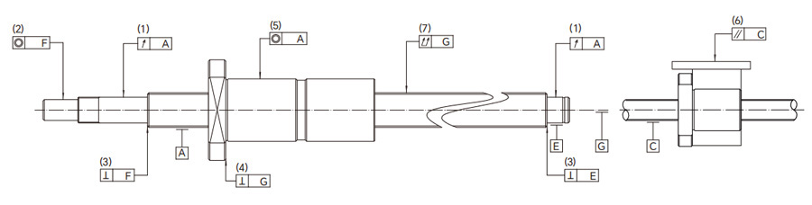
Fig 1.1.2 Mounting Accuracy and Tolerance
1-1-4 Preload Torque
As figure 1.1.3 shown in below, it specified allthe type of preload torque generated by rotating a preloaded ball screw.
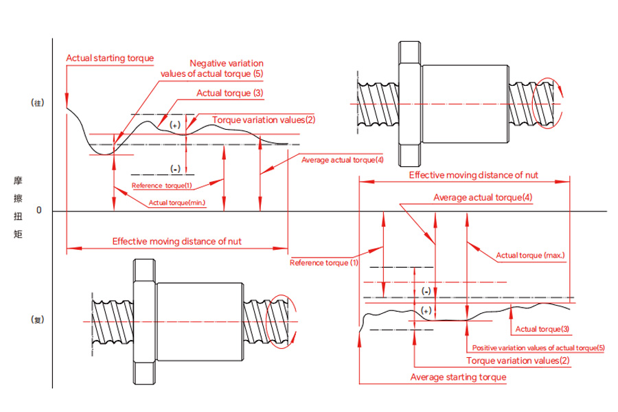
Fig 1.1.3 Descriptions of preload torque
Glossary
1. Preload
To generate the inner force inside the ball screw to decrease the
clearance and increase the rigidity, a set of one gage ( approximately 2μ) larger steel balls is filled inside the nut or two nuts which are executing mutual displacement in axial direction.
2. Preload dynamic torque
The dynamic torque required for continuously rotating the screws shaft or the nuts under unload condition and the preload has applied to the ballscrews.
3. Reference torque
The targeted preload dynamic torque Fig 1.1.3-(1)
4. Torque variation values
The variation values of the targeted preload torque variation rates are specified.Take a positive or negative value relative to the reference torque.
5. Torque variation rate
The variation ratio of reference torque.
6. Actual torque
The actual measured preload dynamic torque of the ball screws.
7. Average actual torque
The arithmetic average of the maximal and minimal actual
torque values measured when the nuts are doing reciprocating
movements.
8. Actual torque variation values
After the nut doing reciprocating movements on the effective
length of the thread, the biggest variation tested will be the actual
torque variation value, which is covered between the positive and negative minimum value relative to the actual torque.
9. Actual torque variation rate
The rate of actual torque variation values in relation of the average
actual torque.
Table 1.1.7 Permissible ranges of toque variation rates
| Reference torque kgf.cm |
Effective threading length mm |
| Below 4000 |
4000~10000 or less |
| Slenderness 1:below 40 |
Slenderness1:40~1:60 |
- |
| Grade |
Grade |
Grade |
| More than |
the following |
C0 |
C1 |
C2,C3 |
C5 |
C0 |
C1 |
C2,C3 |
C5 |
C1 |
C2,C3 |
C5 |
| 2 |
4 |
±35% |
±40% |
±45% |
±55% |
±45% |
±45% |
±55% |
±65% |
- |
- |
- |
| 4 |
6 |
±25% |
±30% |
±35% |
±45% |
±38% |
±38% |
±45% |
±50% |
- |
- |
- |
| 6 |
10 |
±20% |
±25% |
±30% |
±35% |
±30% |
±30% |
±35% |
±40% |
- |
±40% |
±45% |
| 10 |
25 |
±15% |
±20% |
±25% |
±30% |
±25% |
±25% |
±30% |
±35% |
- |
±35% |
±40% |
| 25 |
63 |
±10% |
±15% |
±20% |
±25% |
±20% |
±20% |
±25% |
±30% |
- |
±30% |
±35% |
| 63 |
100 |
- |
- |
±15% |
±20% |
- |
- |
±20% |
±25% |
- |
±25% |
±30% |
Remarks: 1. Slenderness is the value of dividing the screws shaft outside diameter with the screws shaft threading length.

 English
 Português
 русский
 Español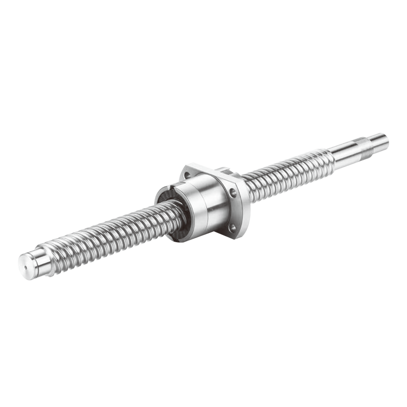
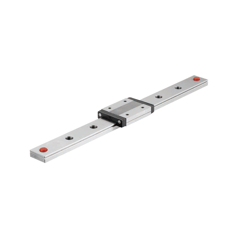 Обзор продукта: миниатюрный размер, широкий корпус Серия MGW-C/H представляет с...
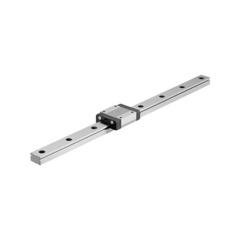 Серия MGN-C/H представляет собой миниатюрную компактную линейную направляющую шаро...
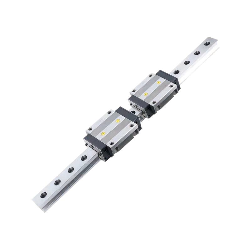 Серия RGW-CC/HC представляет собой высокосборочную широкопрофильную линейную напра...
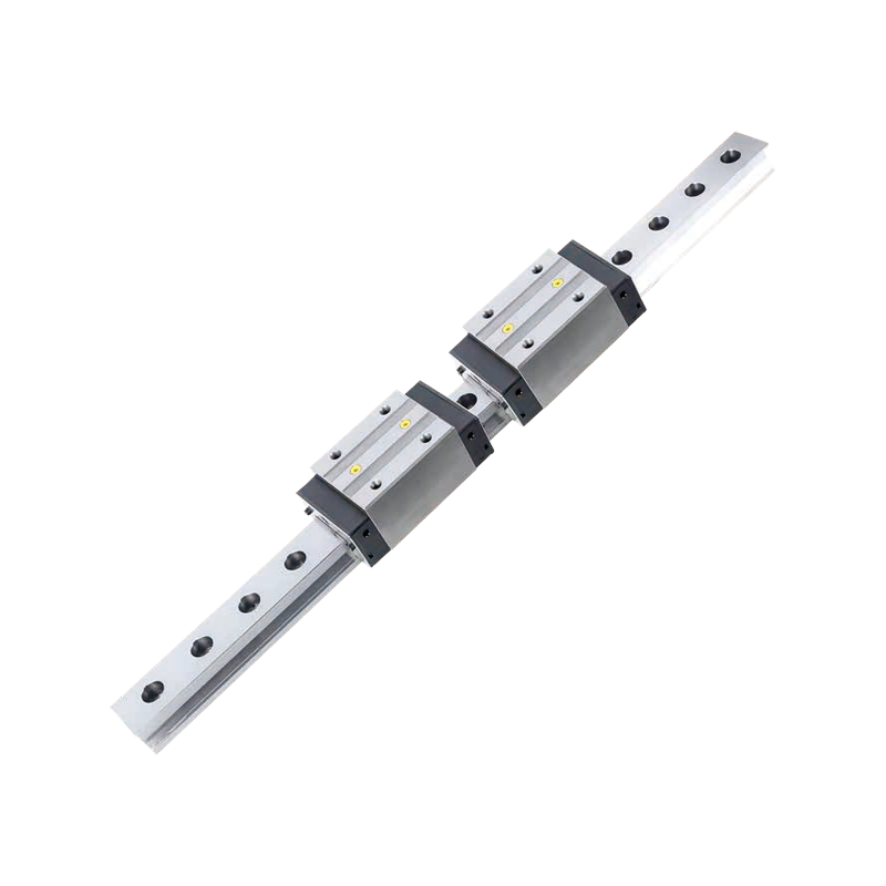 Серия RGH-CA/HA представляет собой роликовые линейные направляющие высокого сбороч...
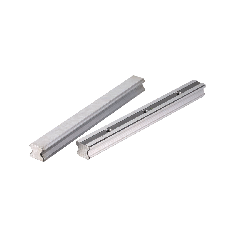 Серия HGR-T представляет собой высокосборную линейную направляющую с нижней фиксир...


